Because of our interest in short waves most of our equipment serves for that. Transmitting gear is the most important, of course.
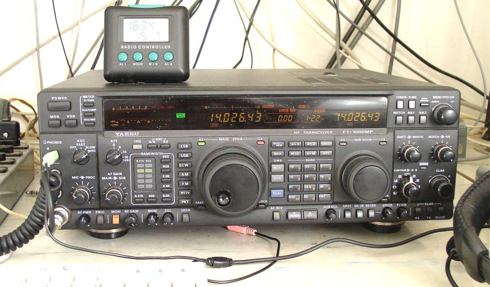
To be able to participate in contest in multiop category 2 independent stations are necessity: running and multiplier stations. Currently used transceiver model at running station is a Yaesu FT1000MP. It offers all most needed features - good receiver, 2nd auxialiary RX, computer control and appropriate operator comfort. It looks like the complexity of control is at highest acceptable level we need, some features offered are useless during contests - it is not enough time to play with them...
The radio at multiplier station is usually lent from some club members - models like Kenwood TS850 or TS450. To minimize interference between the two stations we have built a preselector for multiplier stn (BCC design) that also helps to protect the receiver against damage. FT1000 seems to be less sensitive to signals from different bands (perhaps better band pass filters at front stage) than above mentioned Kenwoods - no preselector is currently used, but it is planned for future.
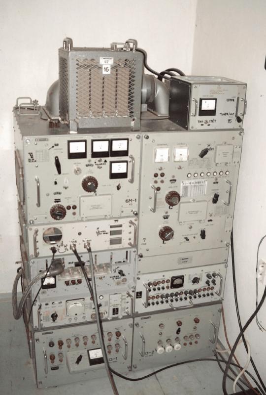
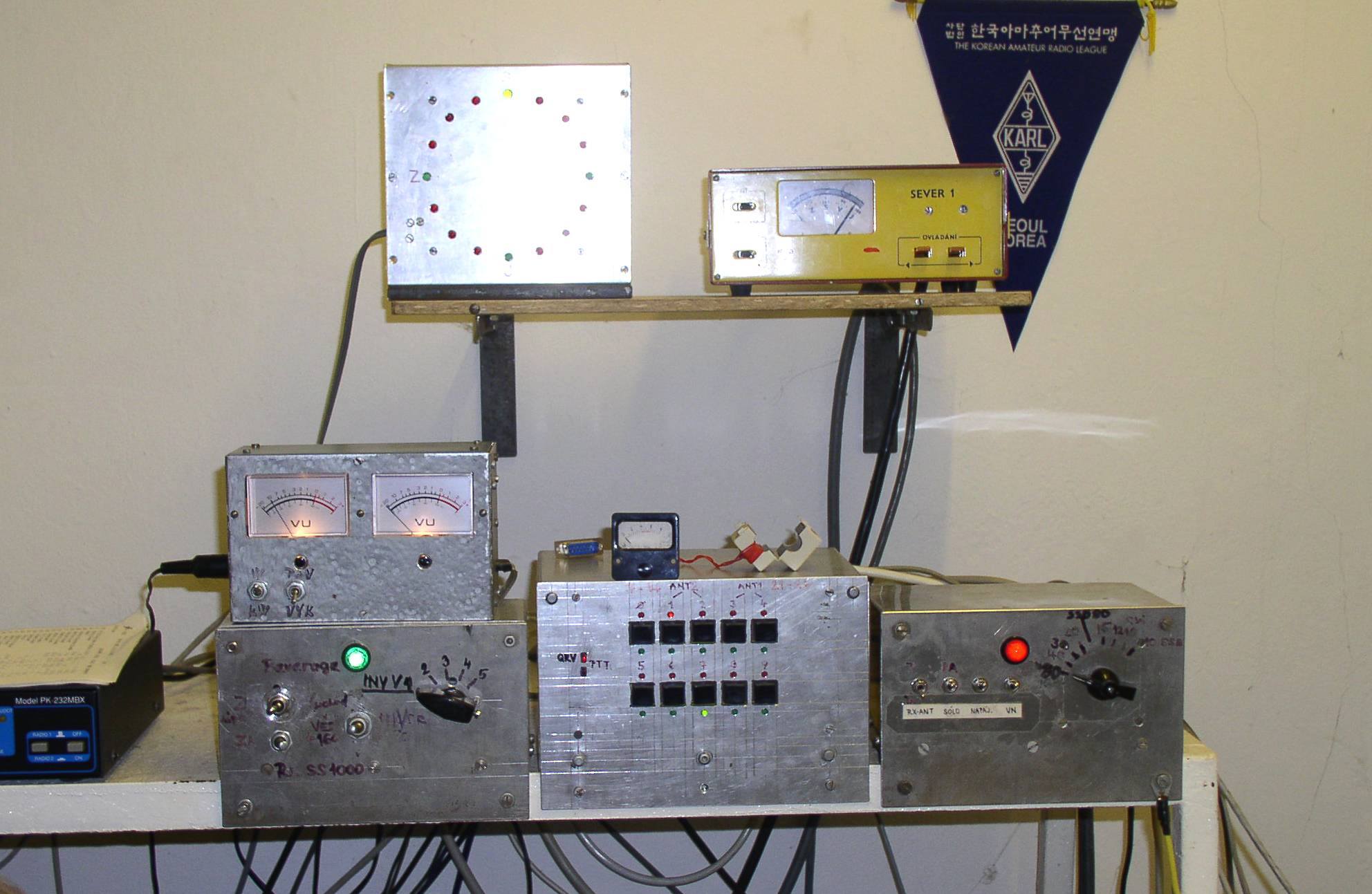
There are 2 separated power amplifiers, one for each station. The running stn employs modified military transmitter R140. There is one tube there - GU34. The exciting power is consumed by resistor, connected to 1st grid. The low impedance guaranties stability of the amplifier (no neutralisation needed). Original antenna tuner of the transmitter is used as well, it is very robust. Output power is around 1kW on all bands 1.8 - 28 MHz. The most interesting feature of the PA is a remote control - 10 pretuned setting (both PA and ant tuner) can be changed quickly (less than 30 sec) just by one remote switch. The system is based on mechanical memories and pin switches. Variable capacitors and coils are controlled by motors, block of capacitors switched by relays. It is necessary to pretune the PA for each setting (switch position) manually, but once done, the change between settings is fast - optimal for contest traffic. The multiplier station's PA is a rebuild commercial transmitter SS1000, manufactured in former GDR, with one glass tube SRS457. We use it for more than 10 years already. It must be tuned manually, covers bands 1.8 - 21 MHz, output power is around 800W. Intention is to replace it by another R140 in future, mostly because of remote control feature.
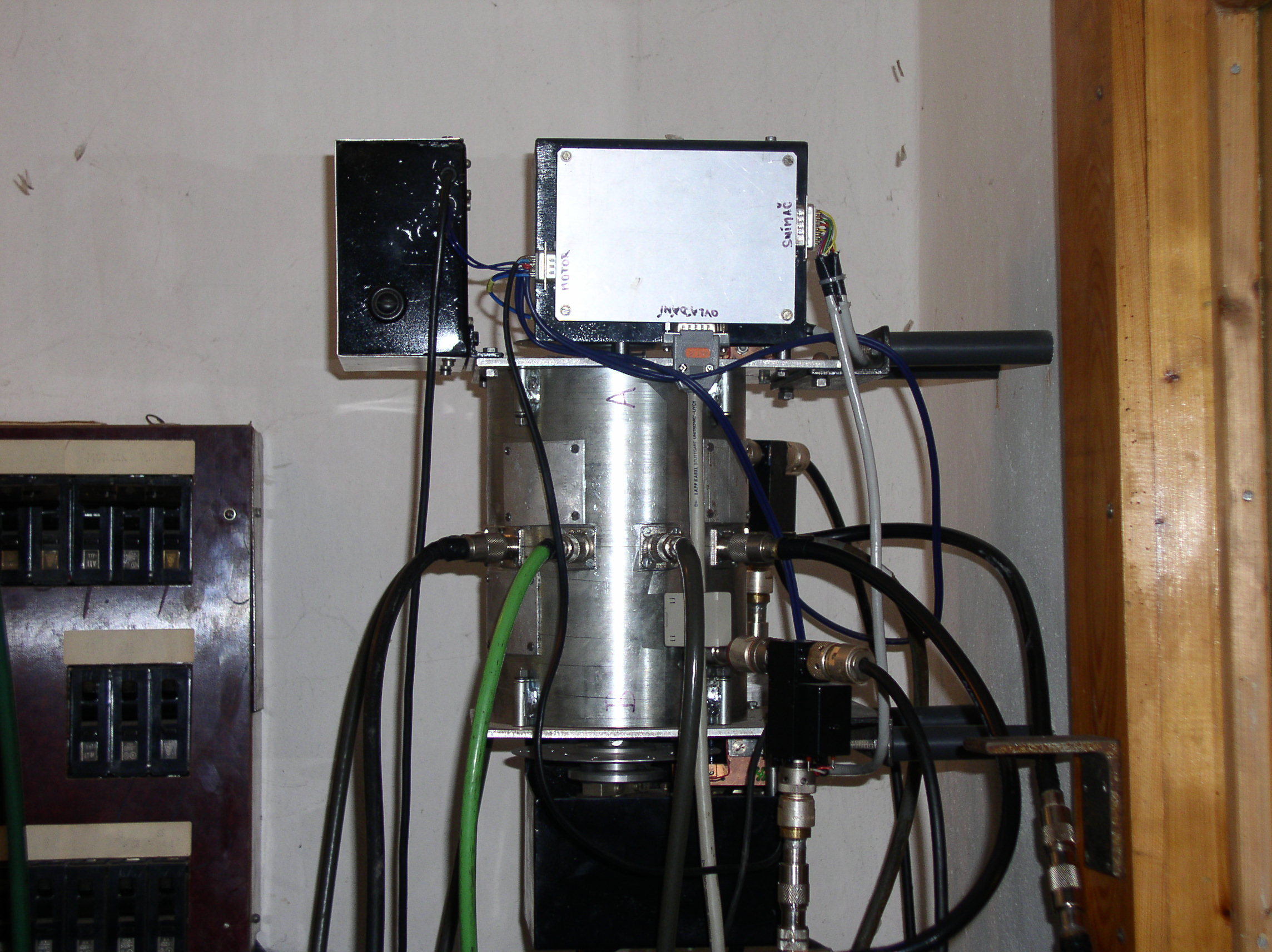
The signal from power amplifiers goes to home made antenna switch.. That small monster should assure commutation of 10 antennas between the two stations in such way that both stations have same priority, should not restrict each other, eliminate the possibility of power from one station going to receiver of the other and it is safe when one station accidentally starts transmission while the switch is moving. It is based on two robust ceramic switching segments, each driven independently by separate DC motor. The system is completed with 2 coaxial relays that connect the station to dummy load (2 separate) while the switch is moving or not powered (nobody in club / station off). The control is accomplished from 2 remote control panels (one at each station) that contain 10 buttons for antenna selection, 10 x 2 LEDs indicating what antenna is connected to run and what to multiplier station and LED indicating the switch is moving. The system has been proved for last several years and replaced completely coax cable mess / manual coax interswitching. The switch parameters are sufficient - the insulation in worst case is more than 40 dB on 28 MHz between neighboring outputs.
The azimuth antenna indicator is closely connected to the antenna switch. There is an angle transducer (homemade) on both main towers - an equipment that reads the angle using photodiodes/transistors and a dish with holes in Gray code (5 bits) and sends the data as continuous serial data stream (only one data wire). That signal goes to control panel of antenna switch and it is commuted together with antennas, so the indicator shows always azimuth of currently connected antenna. Is consists of circle with 16 LEDs (position between 2 LEDs is indicated by light of both LEDs). There are 2 such indicators, one for each station, of course. The antenna switching is independent from PA control.
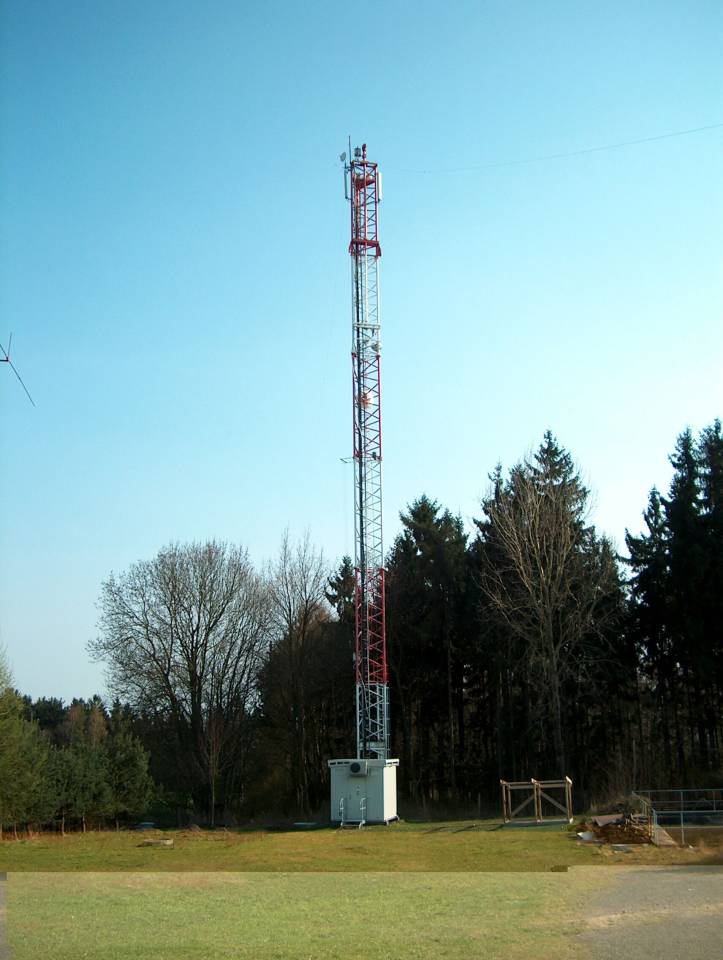
The antenna farm is that that determines the quality of contest station. Most of our antennas are old, constructed in time the club QTH was built. The basis are two towers, smaller 15m high with 6 ele OWA Yagi for 28 MHz above 6 ele Long John Yagi for 21 MHz and the other 20 m tower holding 2 elements HB9CV for 7 MHz above 6 ele Long John Yagi for 14 MHz. The 7/14/21 MHz beams are home made, with steel boom and aluminum elements. As result the antennas are very heavy and manipulation / maintenance is difficult. Fortunately they survive winds and weather very good... Main disadvantage of such arrangement is 2 antennas are always turned together and there is low insulation between the two on same tower, in worst case 20 dB only - it creates a possibility of additional QRM and danger of damage of RX front stage. The rotators are home made as well / robust, powered by 3phase async motors. We have also another 40m tower, currently used as a quarter wave vertical for 1.8 MHz (it is grounded, fed by gamma match), there is an inverted Vee for 3.5 MHz on top of the tower. The tower consists from segments of old crane - 6 segments, each of 1 tone weight. The tower is self supporting, the basement is about 50 cubical meters of concrete. The tower is also hired to GSM mobile phone provider (900 MHz) and to Internet wireless provider. The other already old antenna is a vertical 23m high, used mostly for 3.5 MHz - but it performs well on 1.8, 7 and 10.1 MHz. Recently we have some problems with interference from that antenna to our computer equipment. Next available antenna is a vertical AVT-4 for 7, 14, 21 and 28 MHz, used mostly as supporting antenna for multiplier station. Last antenna worth to note is a 3 ele Yagi for 24.9 MHz on separate 12m tower, used for DX hunting on that band. The only HF band where we have no good antenna is an 18 MHz band. During winter season we use the opportunity and install beverage antennas, one heading east, the other west. The length is about 400m, wire is hanged in about 1m high. There are 2 amplifiers with filters (160 and 80m bands only - to eliminate QRM from medium waves freq range and the other stn operating on bands 7 MHz and above), one for each antenna. The other advantage of the beverage is it does not catch too much QRM from nearby small factory - the vertical antennas are very sensitive to it.
There is also a homemade FM transceiver tuned permanently on local 2m frequency 145.325 MHz, for local communication / net.
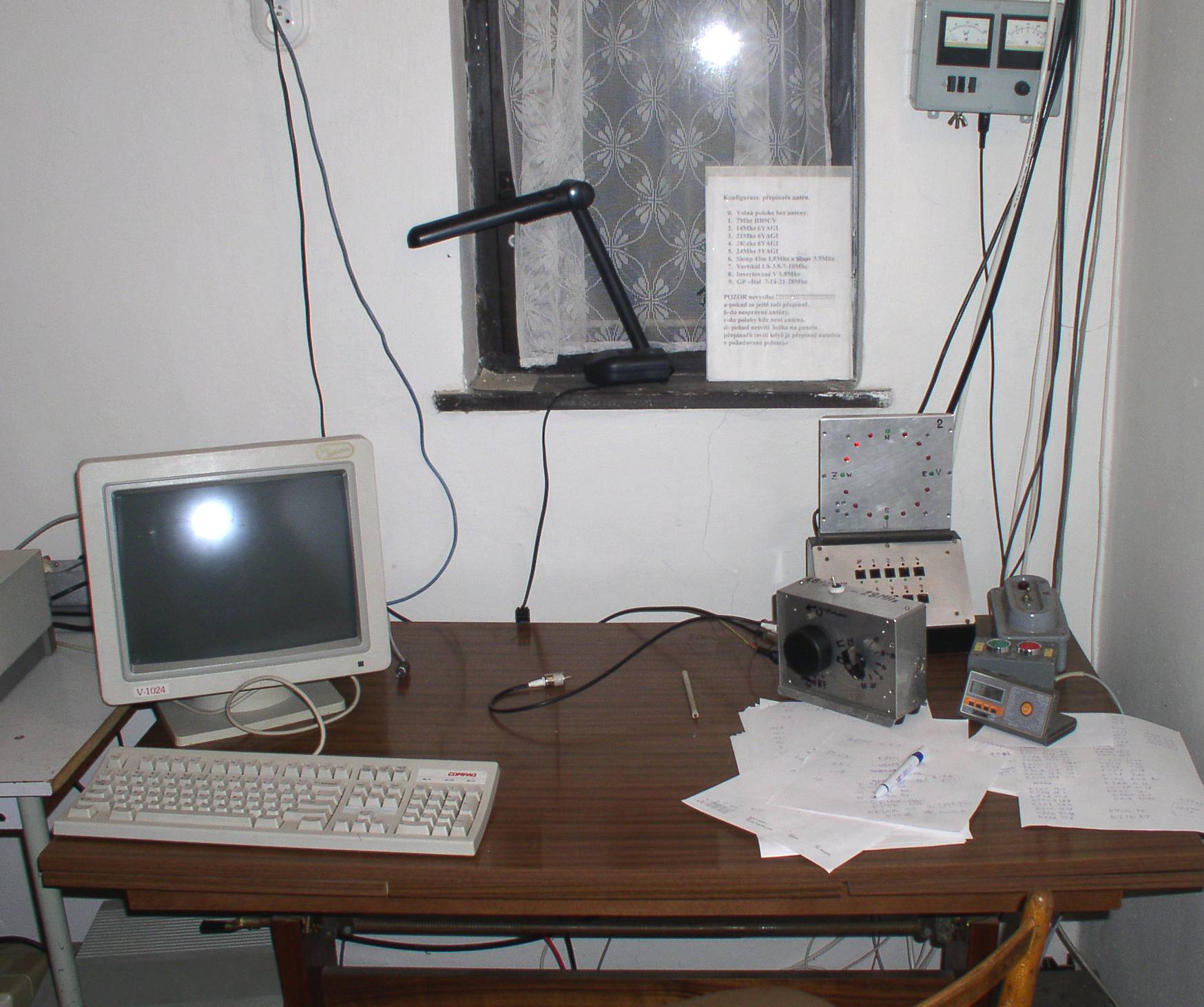
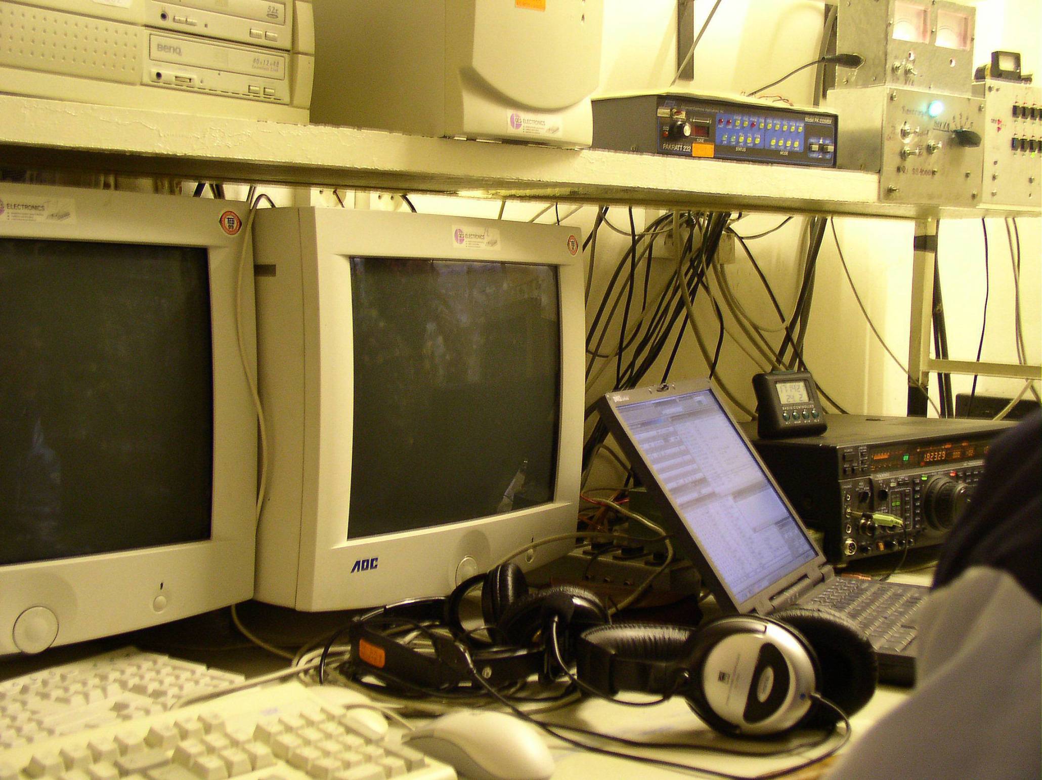
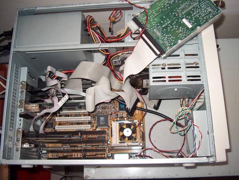
The computer equipment plays very important role in today's contesting - to make a good result without mastering it is nearly impossible. Counts of QSO practically exclude usage of paper logs. We started with computers like Sinclair ZX81, later Commodore C64 and finally IBM PC platform. We have tested several different contest programs (TR, Writelog), but finally we decided to prefer CT from K1EA. There is clear winner among RTTY contest programs - RTTY by WF1B. Computer usage is not without problems - penetration of HF energy into the system often results to wrong function of keyboard, slowing of system clock and in worst case in a crash. There is also another aspect - interference coming from PC to our receivers. We made some experiments with network connection between the two stations / computers - the most stable choice seems to be serial/COM port connection; Ethernet connection is working as well, but less stable. The keying in CW contests goes from PC (via optocopler) connected in parallel with memory elbug with single chip microprocessor (homemade). The RTTY controller used for RTTY contests and DXing is an old PK232MBX - it is used also as 9k6 TNC for DX cluster spots connected directly to SCC card of our node OK0NAL via optocopler (small PK232 modification needed).
Computers are also used for other purposes - we have Internet online connection in our club, allowing easy access to actual DX information, online logs of DXpeditions etc...
There is a packet radio node OK0NAL in our house. It is constructed and maintained with support of club and club members only. There are 2 user access frequencies - 144.950 MHz 1k2 AFSK and 433.650 9k6 FSK (G3RUH standard). The base is a node software PC Flexnet 3.3 running on AMD 75 MHz PC under MS DOS. There is one radio link connection available (70cm to OK0NAD) as well as 2 AXIP/AXUDP links via Internet to OK0NAG and OK0NHD. A BBS (Baycom type) is running in parallel on above mentioned PC, call OK0NAL-8. It is used mostly for messages among club members, but there is also forwarding from another BBS for some message kinds.